

Picture
Contact
Address:Nanning, Guangxi, China
Tel:
Name:
Fax:
Website:https://www.cokgc.com/
E-mail:COMKGC@163.COM
Tel:
Name:
Fax:
Website:https://www.cokgc.com/
E-mail:COMKGC@163.COM
Current:Home > +POT SPAREPARTS
+POT SPAREPARTS
MORNSUN
2016-11-12 22:59:00
.png)
|
CNVTR,CHOPR,DC,E0515S-2W |
CONVERTER,TYPE:CHOPPER,DC,FOR VFC OF POTCONTROLLER,MORNSUN,MDL:E0515S-2W. |
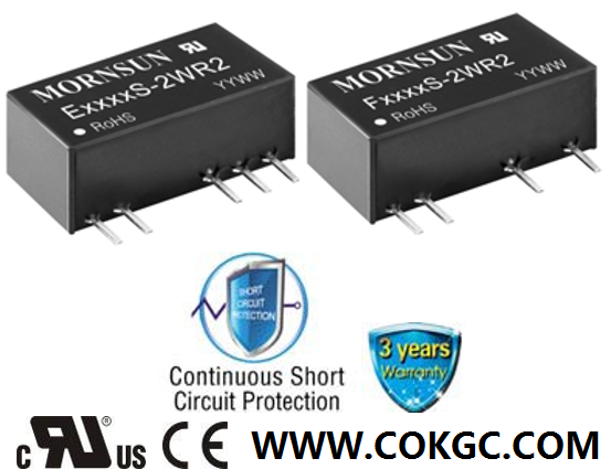
This DC/DC converter from Mornsun is specially designed for applications where an isolated output is required from a distributed power supply system. Equipped with numerous features, including a miniature SIP package, high efficiency and an operating temperature of -40°C to +105°C.
Fixed input voltage
Continuous short circuit protection
RoHS compliant
No external component required
Unregulated
Industry standard pin-out
High power density
Power: 2W
Input: 4.5-5.5V DC
Output: ±15V DC
Outputs: 2
Manufacturer's part E0515S-2WR2
Manu part Input voltage Output voltage
E0503S-2WR2 4.5-5.5V DC ±3.3V DC
E0505S-2WR2 4.5-5.5V DC ±5V DC
E0509S-2WR2 4.5-5.5V DC ±9V DC
E0512S-2WR2 4.5-5.5V DC ±12V DC
E0515S-2WR2 4.5-5.5V DC ±15V DC
E0524S-2WR2 4.5-5.5V DC ±24V DC
E1203S-2WR2 10.8-13.2V DC ±3.3V DC
E1205S-2WR2 10.8-13.2V DC ±5V DC
E1209S-2WR2 10.8-13.2V DC ±9V DC
E1212S-2WR2 10.8-13.2V DC ±12V DC
E1215S-2WR2 10.8-13.2V DC ±15V DC
E1515S-2WR2 13.5-16.5V DC ±15V DC
E2405S-2WR2 21.6-26.4V DC ±5V DC
E2409S-2WR2 21.6-26.4V DC ±9V DC
E2412S-2WR2 21.6-26.4V DC ±12V DC
E2415S-2WR2 21.6-26.4V DC ±15V DC

2W, Fixed input voltage, isolated & unregulated dual /single output FEATURES • Continuous short-circuit protection • Operating temperature range: -40℃ to +105℃ • High efficiency up to 86% • High power density • Miniature SIP package • Isolation voltage: 3K VDC • No external component required • International standard pin-out Patent Protection RoHS E_S-2WR2 & F_S-2WR2 series are specially designed for applications where an isolated voltage is required in a distributed power supply system. They are suitable for 1. Where the voltage of the input power supply is stable (voltage variation: ±10%Vin); 2. Where isolation between input and output is necessary (isolation voltage ≤3000VDC); 3. Where the output voltage regulation and the ripple & noise of the output voltage is not strictly required; 4. Typical application: digit circuit condition; normal low-frequency artificial circuit condition; relay drive circuit and data switching circuit condition, etc. Selection Guide Certification Part No. Input Voltage (VDC) Output Efficiency (%,Min./Typ.) @ Full Load Max. Capacitive Load* (μF) Nominal (Range) Output Voltage (VDC) Output Current (mA)(Max./Min.) -- E0503S-2WR2 5 (4.5-5. 5) ±3.3 ±303/±30 68/72 100 UL/CE E0505S-2WR2 ±5 ±200/±20 76/80 E0509S-2WR2 ±9 ±111/±11 80/84 E0512S-2WR2 ±12 ±83/±8 79/83 E0515S-2WR2 ±15 ±67/±7 78/82 E0524S-2WR2 ±24 ±42/±4 80/84 -- F0503S-2WR2 3.3 400/40 75/79 220 UL/CE F0505S-2WR2 5 400/40 78/82 F0509S-2WR2 9 222/22 78/82 F0512S-2WR2 12 167/17 78/82 F0515S-2WR2 15 133/13 79/83 F0524S-2WR2 24 83/8 80/84 -- E1203S-2WR2 12 (10.8-13.2) ±3.3 ±303/±30 71/75 100 UL/CE E1205S-2WR2 ±5 ±200/±20 76/80 E1209S-2WR2 ±9 ±111/±11 80/84 E1212S-2WR2 ±12 ±83/±8 80/84 E1215S-2WR2 ±15 ±67/±7 80/84 F1205S-2WR2 5 400/40 78/82 220 F1209S-2WR2 9 222/22 77/81 F1212S-2WR2 12 167/17 80/84 F1215S-2WR2 15 133/13 81/85 F1224S-2WR2 24 83/8 82/86 -- E1515S-2WR2 15 (13.5-16.5) ±15 ±67/±7 80/84 100 F1505S-2WR2 5 400/40 76/80 220 F1509S-2WR2 9 222/22 76/80 F1512S-2WR2 12 167/17 77/81 UL/CE E2405S-2WR2 24 (21.6-26.4) ±5 ±200/±20 76/80 100 E2409S-2WR2 ±9 ±111/±11 80/84 E2412S-2WR2 ±12 ±83/±8 80/84 E2415S-2WR2 ±15 ±67/±7 80/84 F2405S-2WR2 5 400/40 76/80 220 F2409S-2WR2 9 222/22 82/86 F2412S-2WR2 12 167/17 80/84 F2415S-2WR2 15 133/13 82/86 -- F2418S-2WR2 18 111/11 82/86 UL/CE F2424S-2WR2 24 83/8 82/86 Note: *The capacitive loads of positive and negative outputs are the same. Input Specifications Item Operating Conditions Min. Typ. Max. Unit Input Current (full load / no-load) 5V input -- 506/35 --/60 mA 12V input -- 208/20 --/50 15V input -- 159/15 --/35 24V input -- 104/10 --/30 Reflected Ripple Current -- 15 -- mA Surge Voltage (1sec. max.) 5V input -0.7 -- 9 VDC 12V input -0.7 -- 18 15V input -0.7 -- 21 24V input -0.7 -- 30 Input Filter Filter capacitor Hot Plug Unavailable Output Specifications Item Operating Conditions Min. Typ. Max. Unit Output Voltage Accuracy See tolerance envelope graph (Fig. 1) Line Regulation Input voltage change: ±1% 3.3VDC output -- -- ±1.5 -- Other output -- -- ±1.2 Load Regulation 10%-100% load 3.3VDC output -- 18 -- % 5VDC output -- 12 -- 9VDC output -- 9 -- 12VDC output -- 8 -- 15VDC/18VDC output -- 7 -- 24VDC output -- 6 -- Ripple & Noise* 20MHz bandwidth -- 75 200 mVp-p Temperature Coefficient Full load -- -- ±0.03 %/℃ Short Circuit Protection** E24xxS-2WR2/F24xxS-2WR2/E0524S-2WR2/F0524S-2WR2 -- -- 1 s Others Continuous, self-recovery Note: * Ripple and noise are measured by “parallel cable” method, please see DC-DC Converter Application Notes for specific operation; **Supply voltage must be discontinued at the end of short circuit duration forE24xxS-2WR2/F24xxS-2WR2 series, and E0524S-2WR2/F0524S-2WR2 models. General Specifications Item Operating Conditions Min. Typ. Max. Unit Isolation Voltage Input-output, with the test time of 1 minute and the leak current lower than 1mA 3000 -- -- VDC Isolation Resistance Input-output, isolation voltage 500VDC 1000 -- -- MΩ Isolation Capacitance Input-output, 100KHz/0.1V E2415S-2WR2/F2424S-2WR2 -- 50 -- pF Other models -- 20 -- Operating Temperature Derating when operating temperature up to 85℃, (see Fig. 2) -40 -- 105 ℃ Storage Temperature -55 -- 125 Casing Temperature Rise Ta=25℃, nominal input, full load output -- 25 -- Pin Welding Resistance Temperature Welding spot is 1.5mm away from the casing, 10 seconds -- -- 300 Storage Humidity Non-condensing -- -- 95 %RH Switching Frequency Full load, nominal input voltage -- 100 -- KHz MTBF MIL-HDFK-217F@25℃ 3500 -- -- K hours Physical Specifications Casing Material Plastic (UL94-V0) Package Dimensions 19.65*7.05*10.16 mm Weight 2.4g (Typ.) Cooling Method Free air convection EMC Specifications EMI CE CISPR22/EN55022 CLASS B (see Fig. 4 for recommended circuit) RE CISPR22/EN55022 CLASS B (see Fig. 4 for recommended circuit) EMS ESD E_S-2WR2 IEC/EN61000-4-2 Contact ±6KV perf. Criteria B F_S-2WR2 IEC/EN61000-4-2 Contact ±8KV perf. Criteria B Typical application If it is required to further reduce input and output ripple, a filter capacitor can be connected to the input and output terminals, see Fig.3. Moreover, choosing suitable filter capacitor is very important , start-up problems may be caused by too large capacitance. To ensured the modules running well, the recommended capacitive load values as shown in Table 1 Recommended capacitive load value table (Table 1) Vin (VDC) Cin (μF) Single Vout (VDC) Cout (μF) Dual Vout (VDC) # (μF) 5 4.7 3.3/5 10 ±3.3/±5 4.7 12/15 2.2 9/12 2.2 ±9/±12 1 24 1 15/18/24 1 ±15/±24 0.47 Note: #The capacitive loads of positive and negative outputs are the same EMC typical recommended circuit (CLASS B) Input voltage (VDC) 5/12/15 24 EMI C1/C2 4.7μF/50V CY -- 1nF/3KV C3 Refer to the Cout in Fig.3 LDM 6.8μH Note: 1. 24V input series, is subject to CY (CY : 1nF/3KV). 2. It is not needed to add the component in the peripheral circuit when parameter with the symbol of "--".1. Output load requirements Note: 1. 24V input series, is subject to CY (CY : 1nF/3KV). 2. It is not needed to add the component in the peripheral circuit when parameter with the symbol of "--". Output load requirements To ensure the module work efficiently and reliably, during the operation, the min. output load should be no less than 10% of the full load. If th actual output power is low, please connect a resister to the output terminal in parallel, with a recommenced resistance which is 10% of th rated power, and derating is required during operation. Pin-Out Pin Single Dual 1 Vin Vin 2 GND GND 5 0V -Vo 6 No Pin 0V 7 +Vo +Vo Notes: 1. Packing information please refer to Product Packing Information which can be downloaded from WWW.COKGC.COM Packing bag number: 58200001; 2. If the product is not operated within the required load range, the product performance cannot be guaranteed to comply with all parameters in the datasheet; 3. The maximum capacitive load offered were tested at nominal input voltage and full load; 4. Unless otherwise specified, parameters in this datasheet were measured under the conditions of Ta=25 ℃ , humidity<75% with nominal input voltage and rated output load; 5. All index testing methods in this datasheet are based on our Company’s corporate standards; 6. The performance parameters of the product models listed in this manual are as above, but some parameters of non-standard model products may exceed the requirements mentioned above. Please contact our technicians directly for specific information; 7. We can provide product customization service; 8. Specifications are subject to change without prior notice. MORNSUN WWW.COKGC.COM COMKGC@163.COM
|
Purchase Process: Mailto:COMKGC@163.COM |
→We quotation |
→Your side confirmed |
→Released PO to us |
→We signed PO |
→You side payment |
→We delivery goods to your side. |
Home | About Us | News | Recruitment | Contact
Copyright © COMKGC@163.COM KGC RESERVED 备案/许可证编号为:桂ICP备2025052475号-1 https://www.cokgc.com/ All Rights Reserved ByNANNING KAIGANG CRANE CO. LTD
